This CPD introduces isolation valves (IVs) that are likely to be found in domestic and commercial HVAC applications. IVs are essential components of every piping system, to allow selective isolation of sections for on-off control, maintenance, removal, and commissioning. There are numerous IVs employed in a commercial system and, as illustrated in Figure 1, even a relatively small sub-system of low temperature heating distribution pipework serving two fan coils will include in the order of 10 IVs.
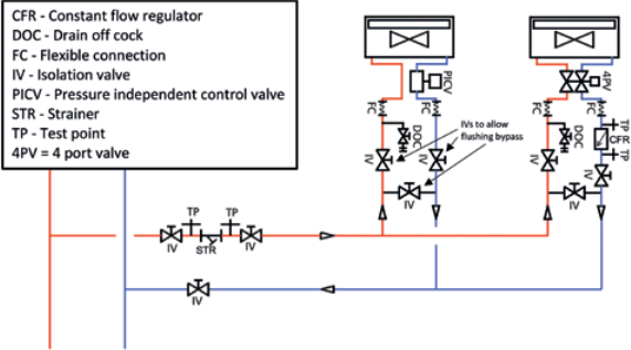
Figure 1: Example of LTHW sub-system serving variable flow terminal units with pressure independent control (hence no double regulating valves). A flushing bypass is located on each terminal branch to allow flow in the main branch pipes to be maximised for the purpose of flushing debris out of the main pipework, in accordance with BSRIA AG 2/20201 (Source: Adapted from CIBSE KS92).
The selection of appropriate IVs is based on parameters that relate to the specific application including the size and type of pipe and the operating pressure inside and across the valve; these are discussed in the boxout ‘DN and PN for pipework components’.
The most common types of isolation valve employed in general HVAC applications are ball valves and butterfly valves. These are well suited to the traditional low-temperature hot water (LTHW), chilled water (CHW) and domestic hot and cold-water services found in commercial and domestic applications – and when closed, they offer a tight seal at their rated differential pressures.
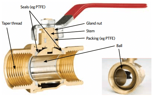
Figure 2: Example of hand-operated full-bore ball valve – open to flow in main image and part closed in inset.
Ball Valves
Ball valves are commonly available in sizes 15mm to 50mm, and are often applied in LTHW, CHW and domestic systems. As illustrated in Figure 2, the ball has a channel through its centre, and the valve stem engages with and rotates the ball. Rotating the ball will vary the degree of opening and with a quarter turn will change the fluid flow path from, typically, full bore to fully closed. (Full bore valves will cost more than reduced bore valves but provide less turbulence and a higher valve coefficient (Kv), so lower operational cost. For an explanation of the impact of Kv see the boxout ‘The cost of pumping through valves and fittings’.)
An example of a 50mm ball valve has a Kv of approximately 300-400. The ball ‘floats’ in the space created by the seals (typically polytetrafluoroethylene (PTFE)) that also provide the bearing for the ball. Water trapped in the channel (within the ball) when the valve is closed can present a risk of freezing and potentially cause splitting of the body, so requires appropriate protection.
Ball valves are normally operated with a hand-operated lever, or they can be automatically controlled with an actuator. As well as circuit isolation, these are often applied as flushing valves, as in Figure 1, to isolate significant plant items when flushing and cleaning. Their robust construction ensures a long, trouble-free service life, producing minimal turbulence in the open position and tight closure in the closed position.
Unless specifically designed to do so, possibly with specifically designed, characterised inserts, a ball valve should not be used as a throttling (regulation) valve.
Butterfly Valves
Butterfly valves, as in the example illustrated in Figure 3, provide a compact solution consisting of a disc that rotates on a shaft at right angles to the fluid flow. When open, the disc is edge-on to the flow and the fluid passes around it, offering limited resistance – an example 50mm butterfly valve has a Kv of approximately 100. These shut off with a quarter turn, either using a direct, simple spindle or employing a gearbox for larger valves. In the closed position, the disc is rotated against a seat in the body of the valve.
Butterfly valves typically take up little more room than a pair of pipe flanges, and are therefore an attractive alternative to the ball valve where space is limited. With an appropriate combination of the elastomer (elastic polymer) liner and disc materials (for example aluminium-bronze, stainless steel and ductile iron), these are suitable for use on CHW, LTHW, and domestic applications.
They are primarily used as on-off valves but can also be used for non-critical throttling applications. Butterfly valves are particularly useful where increased pressure and elevated temperature specifications are outside the normal operating parameters of other isolation valves.
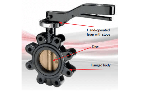
Figure 3: Hand-operated butterfly valve – the aluminium-bronze disc is rotated closed against the resilient liner.
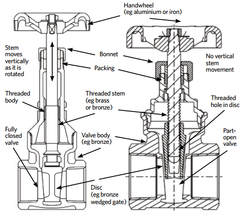
Figure 4: Section through example rising stem (left) and non-rising stem(right) gate valves.
Gate & Globe Valves
Gate and globe valves are better suited to more arduous applications, such as the chemical and pharmaceutical industry, and are also used commonly on medium temperature hot water (MTHW) systems or where higher-pressure rating may be required, such as PN 40. They are often employed as replacements for currently installed systems where the face-to-face dimension needs to match the valve that is being replaced, but they are less frequently used in new projects.
Gate valves employ a gate-like disc, actuated by a stem screw, that moves up and down perpendicular to the water flow. They are available in rising stem and non-rising stem variants, as illustrated in the examples in Figure 4.
For rising stem valves, rotation of the stem drives the stem up and down as the threaded section of the stem turns in the threaded section of the body. The disc is engaged onto the end of the stem (below the threaded section) and rises/falls as the stem unscrews/screws.
The threaded stem in a non-rising stem valve screws directly into a threaded hole, into the core of the disc. As the stem is rotated clockwise, the screw draws the disc upwards, going deeper into the disc core, and so opening the valve. The most significant difference between rising and non-rising is that the opening position of a rising stem valve can be readily observed (since the stem has risen). This will require more space than an equivalent non-rising stem valve (and the stem may be exposed to the elements).
Materials and manufacturing methods employed in modern valves mean that both types have similar operating lives and maintenance needs for HVAC applications.
Gate valves can provide dependable service, particularly where a pressure drop is important. They can allow fluid flow in either direction and the straight-through design offers little resistance to flow, and pressure drop is low. An example 50mm gate valve has a Kv of approximately 280. They should not be used for throttling, since they are not designed to provide a specific control characteristic, and subsequent damage, due to erosion, may prevent the valve subsequently providing an effective shut off.
Globe valves may be used to provide isolation, but can also provide an effective throttling device because seat and disc designs may be selected to provide flow characteristics with proportional relationships between valve lift and flow rate. Globe valve bodies are normally of a spherical shape, ensuring maximum strength against line pressures and pipeline strains. A wide choice of disc and seat materials are available to suit the application. The change in direction of the water flow combined with the restriction in the flow area mean that these valves will impose a large resistance to flow, and hence globe valves have a low Kv value – for example, around 40 for a 50mm valve – and so are not a popular choice as an isolation valve.
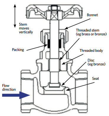
Figure 5: Section through example globe valve
In most cases, IVs are likely to be hand actuated; however, most types may be readily adapted to accept motor actuation. They are typically available with stem extensions to allow, for example, access to a handwheel beyond the thickness of insulation. IVs are normally connected to the pipework by taper thread (such as in Figure 2), flange (such as in Figure 3), or by using a compression or press-fit fitting. Threaded connections may be to UK/European standard BS EN 10226-2 or US-based ANSI B1.20.1 – although these appear similar, they employ a different taper angle and are not interchangeable. All isolation valves include sealing glands and packing to prevent the leakage of water around the stem. Although modern materials, such as PTFE, can provide a long-lasting, robust seal these will still require maintenance, such as tightening of the gland nut (as shown in Figure 2).
Effective and energy-efficient selection of isolation valves in contemporary HVAC systems will require knowledge of the system operating fluid, pressure and temperature; the pipework type and dimensions; the method of jointing/connection (which will relate to the standards being applied in the particular project); and knowledge of the available space – both in the pipe and the surrounding area. This information can then be used to evaluate the most economical IV that meets the performance requirements and, importantly, has the highest value of Kv.
The cost of pumping through valves and fittings
Based on a simplification of the definition as given in CIBSE Guide C3 the valve coefficient (Kv) is the flow of water through a fully open valve, measured in cubic metres per hour, that will induce a pressure loss of 1bar. The flow coefficient (a constant for the open valve) is useful to evaluate the pressure drop at different flow rates as Kv = Q /√Δp where Q is the volume flow rate of water (m3.h-1) through the valve and p = pressure drop across valve (bar), and by converting the units to those more normally used in HVAC applications, volume flow rate of water (L.s-1) and pressure drop (kPa) Kv = 36Q /√Δp and this can be more usefully be reorganised as Δp = (36Q/Kv)2
For example, considering a full bore, butterfly valve, with a Kv of 98 (taken from manufacturer’s data sheet) in a 50mm steel pipe carrying 2kg.s-1 water at 30°C (such as a return LTHW return from an underfloor heating system).
For simplicity, assuming the density of water is approximately 1,000kg.m-3 (actually 995kg.m-3), 2kg.s-1 ≈ 2 L.s-1.
2 = 0.540kPa. A similarly sized ball valve with a Kv of 338 has a pressure drop of (36 x 2/338)2 = 0.045kPa.
(These compare with a pressure loss of 0.190kPa.m-1 in straight 50mm steel pipe.4)
Applying the relationship that power to move water (W) is volume flow (m3.s-1) x ΔP (Pa) indicates that by using the ball valve in place of the butterfly valve will save water power of (2×10-3) x (540 – 45) = 1W.
For continuous operation, 1W of extra water power in the UK is likely to cost in the order of £2 each year for pump power and indirectly add 3kg to CO2 emissions.
DN & PN for pipework components
The nominal pressure (PN or ‘pressure nominale’) is used to specify the required pressure class for a valve. Based on a BS EN standard,5 PN values are quoted in Renard series values, which in HVAC applications are typically the lower values of PN10, PN16, PN25, PN40 and PN50. These indicate the maximum working pressure in bar gauge (at a specific temperature) for the valve, and should be selected for at least the highest pressure that can be developed in the piping in which they are installed. Some valves are rated in terms of ANSI/ASME class – for example, class 150 (which would equate to PN20). However, when considering flange connected valves, the flange hole configurations are not the same in the ANSI/ASME as in the BS EN standards.
The nominal diameter (DN or ‘diamètre nominal’) of valve connections is quoted in millimetres, with values rounded to integers that relate to the physical size of the bore or the outside diameter of the end connection. There is a preferred set of DN values6 that also map to the oft-quoted inch-based US nominal pipe size (NPS) with, for example, the smaller sizes DN 10, DN 15, DN 20, DN 25, DN 32 equating to NPS ⅜” ½”, 1″, 1¼ “. The number following the letters DN does not represent a measurable value and should not be used for calculation purposes, except where specified in a relevant standard.6 So, as an example a DN 50 (2″) pipe has an outside diameter of 60.33 mm (2.375″) – the clear inside diameter will vary with the material and the pressure rating. Components such as valves and pipes with the same DN are dimensionally compatible with one another.
As featured in CIBSE Journal – October 2021