Piping Installation
The below information is compiled from British and International standards on Pipe Threads BS EN 10226 (supercedes BS 21) and Pipe Fittings standards BS EN 10242, BS 143 & 1256 and ISO 49.
Much unnecessary labour and creation of random lengths of pipe might be saved by the application of a few simple figures by the engineer when erecting the pipe line. Generally the pipeline, section by section, is either accommodated within fixed limits, usually the lines of building construction, or is fixed by prescribed dimensions. Except in the case of a continuous run of piping connected either by sockets or flanges, the engineer needs to know the length of pipe required to make up between fixed positions of fittings prior to cutting and threading.
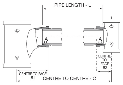
The diagram below and table of ‘A’ dimensions indicates the length of thread engagement of BS EN 10226 taper pipe threads in nominal sizes 1⁄8 to 6 inch.
The approximate pipe length is calculated by using the expression L = C – (B1 + B2) + 2A.
| Fitting Size (Inch) | A (mm) |
|---|---|
| 1/8 | 7 |
| 1/4 | 10 |
| 3/8 | 10 |
| 1/2 | 13 |
| 3/4 | 15 |
| 1 | 17 |
| 1 1/4 | 19 |
| 1 1/2 | 19 |
| 2 | 24 |
| 2 1/2 | 27 |
| 3 | 30 |
| 4 | 36 |
| 5 | 40 |
| 6 | 40 |
Dimensions given do not allow for tapping or threading tolerances.
Pipe Ends
Users are advised to ensure that the external threads on the pipe being screwed into Crane FS fittings are free from damage or any malformation and conform to the gauging requirements of BS EN 10226.
ISO – BS EN – BS identification symbols
| Symbol | Type | Crane Fig No. |
|---|---|---|
| A1 | Elbows | 151 |
| A1/45° | 155 | |
| A4 | 152 | |
| B1 | Tees | 161 |
| – | 163 | |
| C1 | Crosses | 171 |
| D1 | Bends | 193 |
| D4 | 192 | |
| D4/45° | 156 | |
| – | 191 | |
| E1 | Pitcher tees | 199 |
| E2 | Twin elbows | 197 |
| – | Sockets | 176 |
| M2 | 177 | |
| M2 | 179 | |
| M3 | 180 | |
| N4 | Bushes | 140 |
| N8 | Nipples | 144 |
| N8 | 145 | |
| P4 | Back nuts | 150 |
| T2 | Caps | 185 |
| T8 | Plugs | 147 |
| T8 | 148 | |
| T9 | 146 | |
| T11 | 149 | |
| U1 | Unions | 241 |
| U11 | 256 | |
| U11 | 271 | |
| U11 | 289 | |
| U12 | 257 | |
| U12 | 272 | |
| UA11 | Elbow | 261 |
| UA12 | 262 |
Designation of Fitting Size
The designation of fitting size for the fittings shown in this catalogue is as follows: EQUAL FITTINGS: Equal fittings where all outlets are the same size are designated by that one size, irrespective of the number of outlets. UNEQUAL FITTINGS: Unequal fittings (reducing or enlarging) are specified by the sizes of each outlet, the sequence being dependent on the number of outlets:
- For fittings having two outlets, the larger outlet is specified first. Example: Fig. No. 145 hexagon reducing nipple with one end threaded size 2 and other end threaded size 1, is designated 2 x 1.
- For fittings having more than two outlets, Crane FS uses BS EN 10242 method (b) which gives the run as the first and second sizes of the designation and the branch as the third size of the designation. This is in contrast to BS EN 10242 method (a) which gives the run as the first and third sizes of the designation and the branch as the second size of the designation. This method is used in certain international markets. (Please see the diagrams below for a visual explanation). BS EN 10242 method (a) equivalents are specified in this catalogue where applicable.
UK method
BS EN 10242 and ISO 49
Method (b) as used by Crane FS
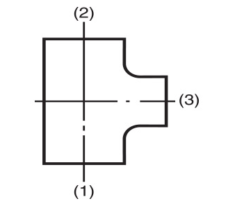
Fig. No. 161 tees
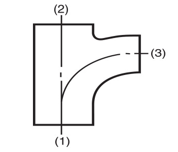
Fig. No. 161 tees
International method
BS EN 10242 and ISO 49
Method (a)
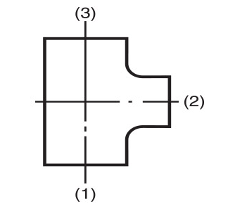
Fig. No. 161 tees
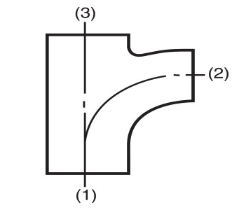
Fig. No. 199 pitcher tees
Malleable Cast Iron
Crane FS malleable iron is of the Blackheart type ideally suited to pipe fitting and manufacture and conforms to BS EN 1562 Designation EN-GJMB-300-6, ASTM A197 and ISO 5922.
Typical properties of Crane FS malleable iron are given in the table below, exceeding the requirements in the above BS EN, ASTM and ISO standards.
| Chemical Composition | Typical |
|---|---|
| Total Carbon | 2.7% |
| Silicon | 1.75% |
| Manganese | 0.69% |
| Sulphur | 0.18% |
| Phosphorous | 0.02% |
| Mechanical Properties | Typical |
|---|---|
| Tensile strength (N/mm2) | 340 |
| Elongation on 36mm (%) | 12 |
| Izod impact (room temp.) (J) | 12 |
| Brinell hardness | 125 |
| Density (g/cm3) | 7.56 |
The close relationship between the physical properties of test bars and actual castings ensures design integrity and the preservation of high safety factors. Shock pressures within pipe systems can be tolerated with complete safety.
The corrosion resistance of Crane FS malleable iron is good when compared with grey cast iron and mild steel for most general applications including water, gas and steam.
Mild Steel
BS 143 and 1256 allow small size (3/8″ and smaller) straight fittings to be supplied in other ferrous materials eg. mild steel, as an alternative to malleable cast iron, providing the mechanical properties are at least equivalent to the specified grade of malleable iron.
Individual data pages state which Crane FS fittings are supplied in mild steel.
Galvanising
Where additional resistance to corrosion is required, malleable cast iron fittings can be hot-dip zinc coated (galvanised) prior to machining. This process involves coating the fittings with zinc which, in addition to its natural resistance to corrosion, provides electrochemical protection where the iron of the fitting is exposed by damage. Mild steel fittings can be supplied with a proprietary zinc-based coating.
The coating weight on Crane FS galvanised fittings conforms to the requirements of BS EN ISO 1461 1998 and ASTM 153 with a minimum coating of 610 g/m2 (2oz/ft2) equal to a thickness of 86μm (0.0034 in).
Average coatings are well in excess of this and exceed the requirements given in BS EN 10242 and ISO 49.
When ordering galvanised or zinc coated fittings add the suffix ‘G’ to the figure number.
View Pipe Fittings